 |
Reference documentation for deal.II version 9.6.0
|
 |
Reference documentation for deal.II version 9.6.0
|

Functions | |
| virtual std::vector< types::manifold_id > | parallel::TriangulationBase< dim, spacedim >::get_manifold_ids () const override |
| void | Triangulation< dim, spacedim >::set_manifold (const types::manifold_id number, const Manifold< dim, spacedim > &manifold_object) |
| void | Triangulation< dim, spacedim >::reset_manifold (const types::manifold_id manifold_number) |
| void | Triangulation< dim, spacedim >::reset_all_manifolds () |
| void | Triangulation< dim, spacedim >::set_all_manifold_ids (const types::manifold_id number) |
| void | Triangulation< dim, spacedim >::set_all_manifold_ids_on_boundary (const types::manifold_id number) |
| void | Triangulation< dim, spacedim >::set_all_manifold_ids_on_boundary (const types::boundary_id b_id, const types::manifold_id number) |
| const Manifold< dim, spacedim > & | Triangulation< dim, spacedim >::get_manifold (const types::manifold_id number) const |
| virtual std::vector< types::manifold_id > | Triangulation< dim, spacedim >::get_manifold_ids () const |
Dealing with boundary and manifold ids | |
| template<int dim, int spacedim> | |
| void | GridTools::copy_boundary_to_manifold_id (Triangulation< dim, spacedim > &tria, const bool reset_boundary_ids=false) |
| template<int dim, int spacedim> | |
| void | GridTools::map_boundary_to_manifold_ids (const std::vector< types::boundary_id > &src_boundary_ids, const std::vector< types::manifold_id > &dst_manifold_ids, Triangulation< dim, spacedim > &tria, const std::vector< types::boundary_id > &reset_boundary_ids={}) |
| template<int dim, int spacedim> | |
| void | GridTools::copy_material_to_manifold_id (Triangulation< dim, spacedim > &tria, const bool compute_face_ids=false) |
| template<int dim, int spacedim> | |
| void | GridTools::assign_co_dimensional_manifold_indicators (Triangulation< dim, spacedim > &tria, const std::function< types::manifold_id(const std::set< types::manifold_id > &)> &disambiguation_function=[](const std::set< types::manifold_id > &manifold_ids) { if(manifold_ids.size()==1) return *manifold_ids.begin();else return numbers::flat_manifold_id;}, bool overwrite_only_flat_manifold_ids=true) |
Dealing with manifold indicators | |
| void | TriaAccessor< structdim, dim, spacedim >::set_manifold_id (const types::manifold_id) const |
| void | TriaAccessor< structdim, dim, spacedim >::set_all_manifold_ids (const types::manifold_id) const |
Dealing with boundary indicators | |
| void | TriaAccessor< 0, 1, spacedim >::set_all_manifold_ids (const types::manifold_id) |
The classes in this group are concerned with the description of the manifold in which the domain that a Triangulation describes lives. This manifold description is necessary in several contexts:
Mesh refinement: Whenever a cell is refined, it is necessary to introduce new vertices in the Triangulation. In the simplest case, one assumes that the objects that make up the Triangulation are straight line segments, a bi-linear surface or a tri-linear volume. The next vertex is then simply put into the middle of the old ones (where "middle" means a suitable average of the locations of the pre-existing vertices). This is the default behavior of the Triangulation class, and is described by the FlatManifold class.
On the other hand, if one deals with curved geometries, or geometries which require a denser refinement in some direction, this is not the appropriate thing to do. The classes derived from the Manifold base class therefore describe the geometry of a domain. One can then attach an object of a class derived from this base class to the Triangulation object using the Triangulation::set_manifold() function associating it with a manifold_id (see types::manifold_id), use this manifold_id on the cells, faces or edges of the triangulation that should be described by this manifold using the TriaAccessor::set_manifold_id() function, and then the Triangulation will ask the manifold object where a new vertex to be located on a cell, face or edge so attributed should be located upon mesh refinement. Several classes already exist to support the most common geometries, e.g., CylindricalManifold, or PolarManifold, which represent respectively the geometry obtained when describing your space in cylindrical coordinates or in polar coordinates. By default, all curved geometries generated using functions in the GridGenerator namespace attach the correct Manifold object to the curved parts of the domain.
Integration: When using higher order finite element methods, it is often necessary to compute cell terms (like cell contributions to the matrix and right hand side of the linear system) using curved approximations of the boundary, rather than the straight line approximation. The actual implementation of such curved elements happens in the Mapping class (see the Mappings between reference and real cell topic), which however obtains its information about the boundary of the domain from the classes described here. The same is, of course, true when integrating boundary terms (e.g., inhomogeneous Neumann boundary conditions).
Domains with nonzero codimension: In cases where a Triangulation is embedded into a higher dimensional space, i.e., whenever the second template argument of the Triangulation class is explicitly specified and larger than the first (for an example, see step-34), the manifold description objects serve as a tool to describe the geometry not only of the boundary of the domain but of the domain itself, in case the domain is a manifold that is in fact curved. In these cases, one can use the Triangulation::set_manifold() function to indicate what manifold description to use when refining the curve, or when computing integrals using high order mappings.
Many other examples, as well as much theoretical underpinning for the implementation in deal.II, is provided in the geometry paper.
In deal.II, a Manifold is seen as a collection of points, together with a notion of distance between points (on the manifold). New points are typically obtained by providing a local coordinate system on the manifold, identifying existing points in the local coordinate system (pulling them back using the local map to obtain their local coordinates), find the new point in the local coordinate system by weighted sums of the existing points, and transforming back the point in the real space (pushing it forward using the local map). The main class that implements this mechanism is the ChartManifold class, and this is the class that users will likely overload for complex geometries.
While this process is non trivial in most cases of interest, for most of the trivial geometries, like cylinders, spheres or shells, deal.II provides reasonable implementations. More complicated examples can be described using the techniques shown in step-53 and step-54.
In the grand scheme of things, the classes of this group interact with a variety of other parts of the library:
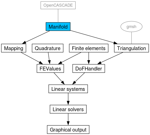
A simple example why dealing with curved geometries is already provided by step-1, though it is not elaborated there. By default, the functions in GridGenerator will attach manifolds to meshes when needed. In each code snippet below we call Triangulation::reset_all_manifolds() to remove these manifolds and handle all Manifold attachment in the example itself to make the impact of the choice of Manifold clear.
Consider this small variation of the second_grid() function shown there, where we simply refine every cell several times:
This code leads to a mesh that looks like this:
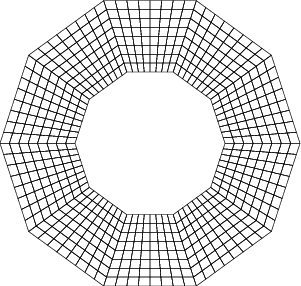
Our intention was to get a mesh that resembles a ring. However, since we did not describe this to the triangulation, what happens is that we start with the 10 coarse cells in circumferential direction we told GridGenerator::hyper_shell() to create, and each of these is then 3 times globally refined. Each time refinement requires a new vertex, it is placed in the middle of the existing ones, regardless of what we may have intended (but omitted to describe in code).
This is easily remedied. Consider this code:
This code is better, producing the following mesh:
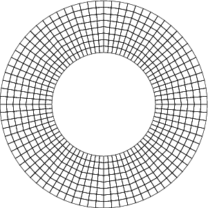
The mesh looks better in that it faithfully reproduces the circular inner and outer boundaries of the domain. However, it is still possible to identify 20 kinks in the tangential lines. They result from the fact that every time a cell is refined, new vertices on interior lines are just placed into the middle of the existing line (the boundary lines are handled differently because we have attached a manifold object). In the first refinement with 10 cells, we got improved points because both outer boundaries have provided a curved description according to the description on blending different manifolds below. In other words, the new points after the first refinement end up in places that may be in the geometric middle of a straight line, but not on a circle around the center.
This can be remedied by assigning a manifold description not only to the lines along the boundary, but also to the radial lines and cells (which, in turn, will inherit it to the new lines that are created upon mesh refinement). This is exactly what GridGenerator::hyper_shell() does by default. For demonstration purposes, we disable the default Manifold behavior and then duplicate it manually:
This leads to the following mesh:
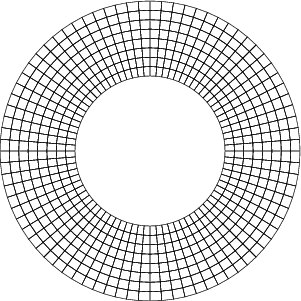
So why does this matter? After all, the last two meshes describe the exact same domain and we know that upon mesh refinement we obtain the correct solution regardless of the choice of cells, as long as the diameter of the largest cell goes to zero.
There are two answers to this question. First, the numerical effort of solving a partial differential equation to a certain accuracy typically depends on the quality of cells since the constant C in error estimates of the form \|u-u_h\|_{H^1} \le Ch^p \|u\|_{H^{p+1}} depends on factors such as the maximal ratio of radii of the smallest circumscribed to largest inscribed circle over all cells (for triangles; or a suitable generalization for other types of cells). Thus, it is worthwhile creating meshes with cells that are as well-formed as possible. This is arguably not so much of an issue for the meshes shown above, but is sometimes an issue. Consider, for example, the following code and mesh:
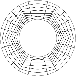
Here, we create only three circumferential cells in the beginning, and refining them leads to the mesh shown. Clearly, we have cells with bad aspect ratios, despite the first refinement that puts the new point into the middle.
If we drive this further and start with a coarse mesh of a much thinner rim between the radii 0.8 and 1.0 and only three cells (which may be inappropriate here, since we know that it is not sufficient, but may also be impossible to avoid for complex geometries generated in mesh generators), we observe the following:
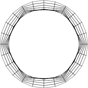
This mesh neither has the correct geometry after refinement, nor do all cells have positive area as is necessary for the finite element method to work. However, even when starting with such an inopportune mesh, we can make things work by attaching a suitable geometry description not only to the boundary but also to interior cells and edges, using the same code as above:
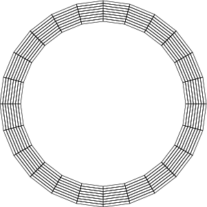
In this last example we finally let GridGenerator do its job and we keep the default manifold configuration, which is a SphericalManifold on every cell and face.
Here, even starting with an initial, inappropriately chosen mesh retains our ability to adequately refine the mesh into one that will serve us well. This example may be manufactured here, but it is relevant, for example in the context of what GridGenerator::hyper_shell() produces in 3d (see the documentation of this function). It is also germane to the cases discussed in the glossary entry on distorted cells.
In a realistic application, it happens regularly that different manifold descriptions need to be combined. The simplest case is when a curved description is only available for the boundary but not for the interior of the computational domain. The manifold description for a ball also falls into this category, as it needs to combine a spherical manifold at the circular part with a straight-sided description in the center of the domain where the spherical manifold is not valid.
In general, the process of blending different manifold descriptions in deal.II is achieved by the so-called transfinite interpolation. Its formula in 2D is, for example, described on Wikipedia. Given a point (u,v) on a chart, the image of this point in real space is given by
\begin{align*} \mathbf S(u,v) &= (1-v)\mathbf c_0(u)+v \mathbf c_1(u) + (1-u)\mathbf c_2(v) + u \mathbf c_3(v) \\ &\quad - \left[(1-u)(1-v) \mathbf x_0 + u(1-v) \mathbf x_1 + (1-u)v \mathbf x_2 + uv \mathbf x_3 \right] \end{align*}
where \bf x_0, \bf x_1, \bf x_2, \bf x_3 denote the four vertices bounding the image space and \bf c_0, \bf c_1, \bf c_2, \bf c_3 are the four curves describing the lines of the cell.
If we want to find the center of the cell according to the manifold (that is also used when the grid is refined), the chart is the unit cell (0,1)^2 and we want to evaluate this formula in the point (u,v) = (0.5, 0.5). In that case, \mathbf c_0(0.5) is the position of the midpoint of the lower face (indexed by 2 in deal.II's ordering) that is derived from its own manifold, \mathbf c_1(0.5) is the position of the midpoint of the upper face (indexed by 3 in deal.II), \mathbf c_2(0.5) is the midpoint of the face on the left (indexed by 0), and \mathbf c_3(0.5) is the midpoint of the right face. In this formula, the weights equate to \frac{\displaystyle 1}{\displaystyle 2} for the four midpoints in the faces and to -\frac{\displaystyle 1}{\displaystyle 4} for the four vertices. These weights look weird at first sight because the vertices enter with negative weight but the mechanism does what we want: In case of a cell with curved description on two opposite faces but straight lines on the other two faces, the negative weights of -\frac{\displaystyle 1}{\displaystyle 4} in the vertices balance with the center of the two straight lines in radial direction that get weight \frac{\displaystyle 1}{\displaystyle 2}. Thus, the average is taken over the two center points in curved direction, exactly placing the new point in the middle.
In three spatial dimensions, the weights are +\frac{\displaystyle 1}{\displaystyle 2} for the face midpoints, -\frac{\displaystyle 1}{\displaystyle 4} for the line mid points, and \frac{\displaystyle 1}{\displaystyle 8} for the vertices, again balancing the different entities. In case all the surrounding of a cell is straight, the formula reduces to the obvious weight \frac{\displaystyle 1}{\displaystyle 8} on each of the eight vertices.
In the MappingQGeneric class, a generalization of this concept to the support points of a polynomial representation of curved cells, the nodes of the Gauss-Lobatto quadrature, is implemented by evaluating the boundary curves in the respective Gauss-Lobatto points (u_i,v_i) and combining them with the above formula. The weights have been verified to yield optimal convergence rates \mathcal O(h^{k+1}) also for very high polynomial degrees, say k=10.
In the literature, other boundary descriptions are also used. Before version 9.0 deal.II used something called Laplace smoothing where the weights that are applied to the nodes on the circumference to get the position of the interior nodes are determined by solving a Laplace equation on the unit element. However, this led to boundary layers close to the curved description, i.e., singularities in the higher derivatives of the mapping from unit to real cell.
If the transition from a curved boundary description to a straight description in the interior is done wrong, it is typically impossible to achieve high order convergence rates. For example, the Laplace smoothing inside a single cell leads to a singularity in the fourth derivative of the mapping from the reference to the real cell, limiting the convergence rate to 3 in the cells at the boundary (and 3.5 if global L2 errors were measured in 2D). Other more crude strategies, like completely ignoring the presence of two different manifolds and simply computing the additional points of a high-order mapping in a straight coordinate system, could lead to even worse convergence rates. The current implementation in deal.II, on the other hand, has been extensively verified in this respect and should behave optimally.
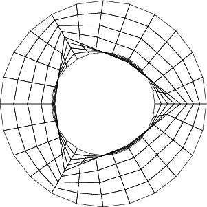
A bad strategy for blending a curved boundary representation with flat interior representations obviously also reflects mesh quality. For example, the above case with only 3 circumferential cells leads to the following mesh with Laplace manifold smoothing rather than the interpolation from the boundary as is implemented in deal.II:
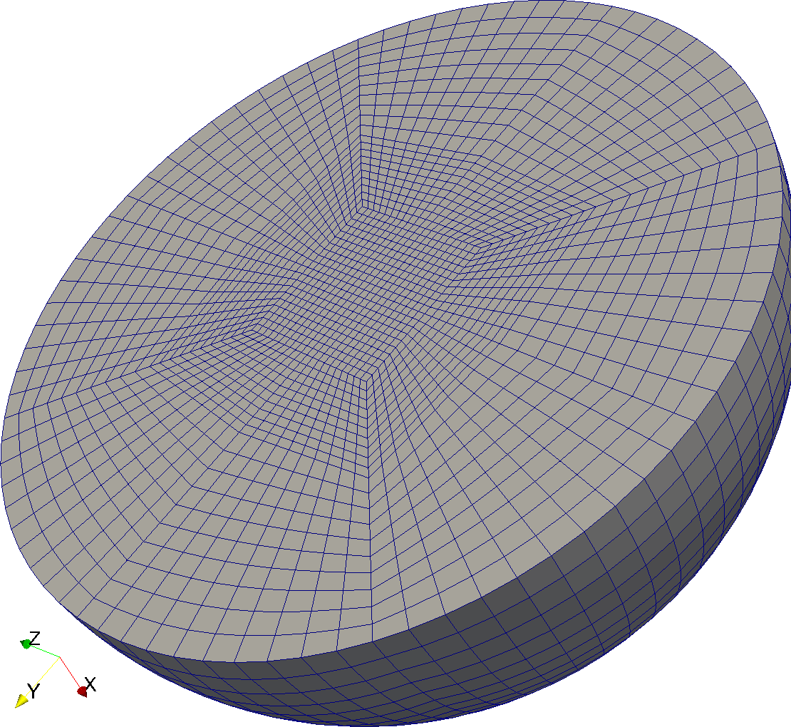
To use a more practical example, consider the refinement of a ball with a SphericalManifold attached to the spherical surface. The Laplace-type smoothing gives the following rather poor mesh:
If we, instead, use the weights derived from transfinite interpolation, the situation is considerably improved:
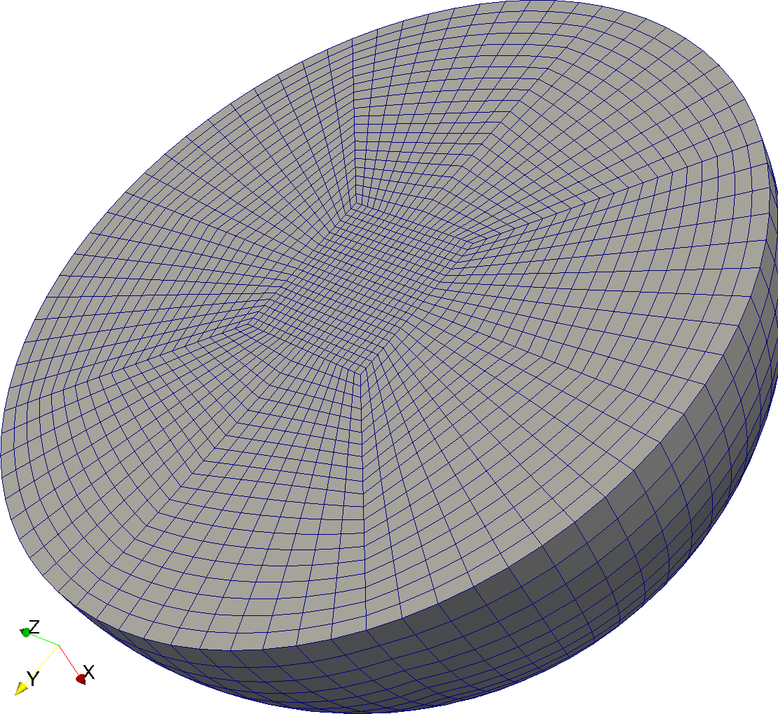
Of course, one could get even better meshes by applying the TransfiniteInterpolationManifold to the whole domain except the boundary where SphericalManifold is attached, as shown by the figures in that class, but in principle, the mesh smoothing implemented in deal.II is as good as it can get from a boundary description alone.
|
overridevirtual |
Return a vector containing all manifold indicators assigned to the objects of the active cells of this Triangulation. Note, that each manifold indicator is reported only once. The size of the return vector will represent the number of different indicators (which is greater or equal one).
Reimplemented from Triangulation< dim, dim >.
Definition at line 386 of file tria_base.cc.
| void GridTools::copy_boundary_to_manifold_id | ( | Triangulation< dim, spacedim > & | tria, |
| const bool | reset_boundary_ids = false ) |
Copy boundary ids to manifold ids on faces and edges at the boundary. The default manifold_id for new Triangulation objects is numbers::flat_manifold_id. This function copies the boundary_ids of the boundary faces and edges to the manifold_ids of the same faces and edges, allowing the user to change the boundary_ids and use them for boundary conditions regardless of the geometry, which will use manifold_ids to create new points. Only active cells will be iterated over. This is a function you'd typically call when there is only one active level on your Triangulation. Mesh refinement will then inherit these indicators to child cells, faces, and edges.
The optional parameter reset_boundary_ids, indicates whether this function should reset the boundary_ids of boundary faces and edges to its default value 0 after copying its value to the manifold_id. By default, boundary_ids are left untouched.
Definition at line 2801 of file grid_tools.cc.
| void GridTools::map_boundary_to_manifold_ids | ( | const std::vector< types::boundary_id > & | src_boundary_ids, |
| const std::vector< types::manifold_id > & | dst_manifold_ids, | ||
| Triangulation< dim, spacedim > & | tria, | ||
| const std::vector< types::boundary_id > & | reset_boundary_ids = {} ) |
Map the given boundary ids to the given manifold ids on faces and edges at the boundary.
This function copies the boundary ids of the boundary faces and edges that are present in the parameter src_boundary_ids to the corresponding manifold id in dst_manifold_ids, of the same faces and edges.
If the optional parameter reset_boundary_ids is non empty, each boundary id in src_boundary_ids, is replaced with the corresponding boundary id in reset_boundary_ids.
An exception is thrown if the size of the input vectors do not match. If a boundary id indicated in src_boundary_ids is not present in the triangulation, it is simply ignored during the process.
Definition at line 2826 of file grid_tools.cc.
| void GridTools::copy_material_to_manifold_id | ( | Triangulation< dim, spacedim > & | tria, |
| const bool | compute_face_ids = false ) |
Copy material ids to manifold ids. The default manifold_id for new Triangulation objects is numbers::flat_manifold_id. When refinements occurs, the Triangulation asks where to locate new points to the underlying manifold.
When reading a Triangulation from a supported input format, typical information that can be stored in a file are boundary conditions for boundary faces (which we store in the boundary_id of the faces), material types for cells (which we store in the material_id of the cells) and in some cases subdomain ids for cells (which we store in the subdomain_id of the cell).
If you read one of these grids into a Triangulation, you might still want to use the material_id specified in the input file as a manifold_id description. In this case you can associate a Manifold object to internal cells, and this object will be used by the Triangulation to query Manifold objects for new points. This function iterates over active cells and copies the material_ids to the manifold_ids.
The optional parameter compute_face_ids, indicates whether this function should also set the manifold_ids of the faces (both for internal faces and for faces on the boundary). If set to true, then each face will get a manifold_id equal to the minimum of the surrounding manifold_ids, ensuring that a unique manifold id is selected for each face of the Triangulation. By default, face manifold_ids are not computed.
Definition at line 2893 of file grid_tools.cc.
| void Triangulation< dim, spacedim >::set_manifold | ( | const types::manifold_id | number, |
| const Manifold< dim, spacedim > & | manifold_object ) |
Assign a manifold object to a certain part of the triangulation. If an object with manifold number number is refined, this object is used to find the location of new vertices (see the results section of step-49 for a more in-depth discussion of this, with examples). It is also used for non-linear (i.e.: non-Q1) transformations of cells to the unit cell in shape function calculations.
A copy of manifold_object is created using Manifold<dim, spacedim>::clone() and stored internally.
It is possible to remove or replace a Manifold object during the lifetime of a non-empty triangulation. Usually, this is done before the first refinement and is dangerous afterwards. Removal of a manifold object is done by reset_manifold(). This operation then replaces the manifold object given before by a straight manifold approximation.
| void Triangulation< dim, spacedim >::reset_manifold | ( | const types::manifold_id | manifold_number | ) |
Reset those parts of the triangulation with the given manifold_number to use a FlatManifold object. This is the default state of a non-curved triangulation, and undoes assignment of a different Manifold object by the function Triangulation::set_manifold().
manifold_number will still have the same ID after calling this function so that the function get_manifold_ids() will still return the same set of IDs.| void Triangulation< dim, spacedim >::reset_all_manifolds | ( | ) |
Reset all parts of the triangulation, regardless of their manifold_id, to use a FlatManifold object. This undoes assignment of all Manifold objects by the function Triangulation::set_manifold().
| void Triangulation< dim, spacedim >::set_all_manifold_ids | ( | const types::manifold_id | number | ) |
Set the manifold_id of all cells and faces to the given argument.
| void Triangulation< dim, spacedim >::set_all_manifold_ids_on_boundary | ( | const types::manifold_id | number | ) |
Set the manifold_id of all boundary faces to the given argument.
| void Triangulation< dim, spacedim >::set_all_manifold_ids_on_boundary | ( | const types::boundary_id | b_id, |
| const types::manifold_id | number ) |
Set the manifold_id of all boundary faces and edges with given boundary_id b_id to the given manifold_id number.
| const Manifold< dim, spacedim > & Triangulation< dim, spacedim >::get_manifold | ( | const types::manifold_id | number | ) | const |
Return a constant reference to a Manifold object used for this triangulation. number is the same as in set_manifold().
|
virtual |
Return a vector containing all manifold indicators assigned to the objects of the active cells of this Triangulation. Note, that each manifold indicator is reported only once. The size of the return vector will represent the number of different indicators (which is greater or equal one).
Reimplemented in parallel::TriangulationBase< dim, spacedim >, parallel::TriangulationBase< dim, dim >, and parallel::TriangulationBase< dim, spacedim >.
| void TriaAccessor< structdim, dim, spacedim >::set_manifold_id | ( | const types::manifold_id | ) | const |
Set the manifold indicator. The same applies as for the manifold_id() function.
Note that it only sets the manifold object of the current object itself, not the indicators of the ones that bound it, nor of its children. For example, in 3d, if this function is called on a face, then the manifold indicator of the 4 edges that bound the face remain unchanged. If you want to set the manifold indicators of face, edges and all children at the same time, use the set_all_manifold_ids() function.
| void TriaAccessor< structdim, dim, spacedim >::set_all_manifold_ids | ( | const types::manifold_id | ) | const |
Do as set_manifold_id() but also set the manifold indicators of the objects that bound the current object. For example, in 3d, if set_manifold_id() is called on a face, then the manifold indicator of the 4 edges that bound the face remain unchanged. On the other hand, the manifold indicators of face and edges are all set at the same time using the current function.
| void TriaAccessor< 0, 1, spacedim >::set_all_manifold_ids | ( | const types::manifold_id | ) |
Set the manifold indicator of this object and all of its lower-dimensional sub-objects. Since this object only represents a single vertex, there are no lower-dimensional object and this function is equivalent to calling set_manifold_id() with the same argument.
| void GridTools::assign_co_dimensional_manifold_indicators | ( | Triangulation< dim, spacedim > & | tria, |
| const std::function< types::manifold_id(const std::set< types::manifold_id > &)> & | disambiguation_function = [](const std::set<types::manifold_id> &manifold_ids) { if (manifold_ids.size() == 1) return *manifold_ids.begin(); else return numbers::flat_manifold_id; }, | ||
| bool | overwrite_only_flat_manifold_ids = true ) |
Propagate manifold indicators associated with the cells of the Triangulation tria to their co-dimension one and two objects.
This function sets the manifold_id of faces and edges (both on the interior and on the boundary) to the value returned by the disambiguation_function method, called with the set of manifold indicators of the cells that share the same face or edge.
By default, the disambiguation_function returns numbers::flat_manifold_id when the set has size greater than one (i.e., when it is not possible to decide what manifold indicator a face or edge should have according to the manifold indicators of the adjacent cells) and it returns the manifold indicator contained in the set when it has dimension one (i.e., when all adjacent cells and faces have the same manifold indicator).
The parameter overwrite_only_flat_manifold_ids allows you to specify what to do when a face or an edge already has a manifold indicator different from numbers::flat_manifold_id. If the flag is true, the edge or face will maintain its original manifold indicator. If it is false, then also the manifold indicator of these faces and edges is set according to the return value of the disambiguation_function.
Definition at line 2921 of file grid_tools.cc.